Before we get started
Before we get started, there are a few things we need to do to make sure your MIDI footswitch stays in tip-top shape!
Use the right MIDI cable
Darkglass amplifiers Exponent 500 and Infinity 500 Combo:
- Use the 7-pin MIDI cable. MIDI Footswitch will be powered by the amplifier.
Other MIDI equipment:
- Use the 7-pin to 5-pin MIDI adapter cable and use the 7-pin connector on the MIDI Footswitch end of the connection.
- Use a 5-pin MIDI cable.
When using the 7-pin MIDI cable, connect 7-pin connectors only to Darkglass devices.
Update to the latest firmware
To get the best experience with your new MIDI Footswitch, it is advised to start with updating the firmware by connecting to the Darkglass Suite via USB. With updated firmware you get access to all the MIDI Footswitch features and latest bug fixes.
Getting started
Top Panel Features
5 footswitches for 5 main and 5×5 sub layer actions
Back Panel Features
MIDI OUT/THRU
7/5-pin DIN connector
- Connects to Darkglass amplifiers or pedals that have a MIDI IN connection
- When connected to a Darkglass e500 or Infinity Combo with a 7-pin MIDI cable no external power supply is required!
- Can be used with 5-pin MIDI cable for connecting to any other generic MIDI device
MIDI IN
5-pin DIN connector
- Connects to a MIDI OUT on another MIDI device
- Passes the MIDI messages through to MIDI OUT/THRU connector
USB
USB-C connector
- Connects to a computer for setting the configuration using Darkglass Suite
- Can be directly connected to the Darkglass e500 amplifier for syncing settings
- Can be used to provide power to the footswitch from USB power banks or chargers.
9V DC
Barrel jack connector (center negative)
- Can be used with a generic power supply (min. 15 mA)
Darkglass Amplifier
1⁄4” TS jack connector
- Connects to the FOOTSWITCH connector of Darkglass amplifiers.
- Works as a Darkglass Super Intelligent Footswitch
- No external power supply is required!
Default configuration
The factory configuration of the MIDI Footswitch sends the default MIDI messages of the Infinity 500 Combo and Exponent 500 presets 1-5. (MIDI Channel 1, Program change 2-6)
Mute messages are enabled meaning that pressing the footswitch of the already selected preset mutes the amplifier and enables the Tuner. (MIDI Channel 1, Program change 1)
Using as Super Intelligent Footswitch
To use the MIDI footswitch like a Darkglass Super Intelligent Footswitch, connect the footswitch to any Darkglass amplifier that has a 1/4“ connector for a footswitch. Do not connect any other cables to the MIDI Footswitch at the same time.
The Super Intelligent Footswitch mode of the MIDI Footswitch can be recognized by the blue LEDs. The first four footswitches from left to right correspond to the four footswitches of the Super Intelligent Footswitch and AO Super Intelligent Footswitch:
| Footswitch | Super Intelligent Footswitch action | A·O Super Intelligent Footswitch action |
| 1 | CLEAN | A |
| 2 | VMT | B |
| 3 | B3K | C |
| 4 | MUTE | MUTE |
Unmute can be done either with MUTE or by choosing any of the three channels. When MUTE is on, another LED (blinking) will show which channel the amplifier will return to when pressing the MUTE again to unmute.
Using the Darkglass Suite
Download the latest Darkglass Suite from our website darkglass.com/suite
Connecting to the Suite
After launching the Suite software, please connect your MIDI footswitch with the included USB type C cable to your computer.
The footswitch can operate via USB power provided on the connection and as soon as it is recognized from your system, the LEDs will indicate the powered state.
Setting up for a Darkglass Device
Selecting the “Set up for a Darkglass device” allows for the default MIDI configuration of the following devices:
Programmable Line
- Aggressively Distorted Advanced Machine
- Alpha Omega Photon
- Microtubes Infinity
Amplifiers
- Exponent 500
- Infinity 500 combo
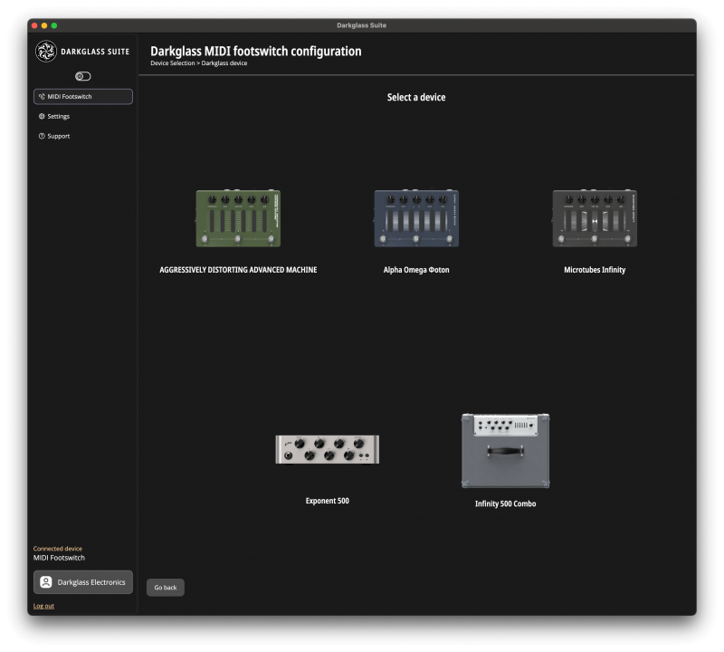
Programmable line
For the programmable line of pedals, the default configuration includes the Presets D, E, F, and Tuner and Bypass toggles.
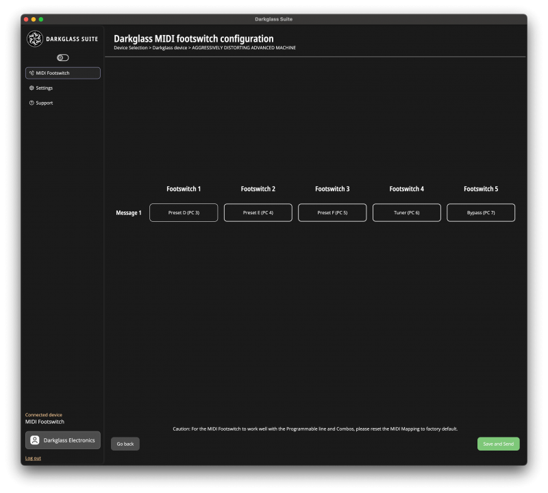
By clicking a message, the message for the corresponding footswitch can be changed to one of the presets A-F, Tuner or Bypass:

- Press the Save and Send button to apply the configuration to the MIDI Footswitch.
Please reset the MIDI mapping of your Programmable line pedal to factory default for these configurations to work properly.
Exponent 500
MIDI Footswitch can automatically sync with Exponent 500 allowing you to change presets and bypass effects. Follow these steps to sync:
- Enable Exponent 500 Sync in the Darkglass Suite if not yet enabled. The state of waiting for first sync is indicated by multicolored waves moving across the LEDs (from firmware 1.3 onwards).
- Connect the Darkglass Suite to Exponent 500 to bind effect bypasses to footswitches per preset (see below for details).
- Connect MIDI Footswitch to Exponent 500 via 7-pin MIDI cable to keep it powered during the sync.
- Connect MIDI Footswitch to Exponent 500 via USB-C to sync. MIDI Footswitch LEDs will flash to indicate the sync and will have the colors of the Exponent 500 presets when ready.
- The USB cable can now be disconnected and Exponent 500 can be controlled with the MIDI Footswitch via 7-pin MIDI cable.
After syncing, the MIDI footswitch operates as follows:
Top page (Presets 1-5)
- On the top page right after syncing, each footswitch LED has the color of the E500 preset. Pressing a footswitch switches to that preset indicated by brighter LED.
- Tapping the footswitch of the already chosen preset again enables mute, giving you also access to the Tuner. Muted channel is indicated by a blinking LED (from firmware 1.3 onwards).
Sub pages (Effects on/off 1-5)
- Long pressing a footswitch switches to the corresponding preset and enters the page of that preset. Each lit up LED corresponds to one effect block, the color corresponding to the effect type color as shown also on the E500 Suite. You can now turn the individual effects on and off using the footswitches. LED brightness will indicate whether the effect is on or off.
- Return to the top page preset selection by long pressing any footswitch.
Binding footswitches to effect bypasses in Exponent 500 Suite
Connect the E500 to the Suite (via USB to desktop version or via Bluetooth to mobile version) to bind the footswitches to effect bypasses. Click the top right MIDI Footswitch button in the Signal Chain tab:

- In the window that opens, you can bind the effect bypasses to the footswitches:
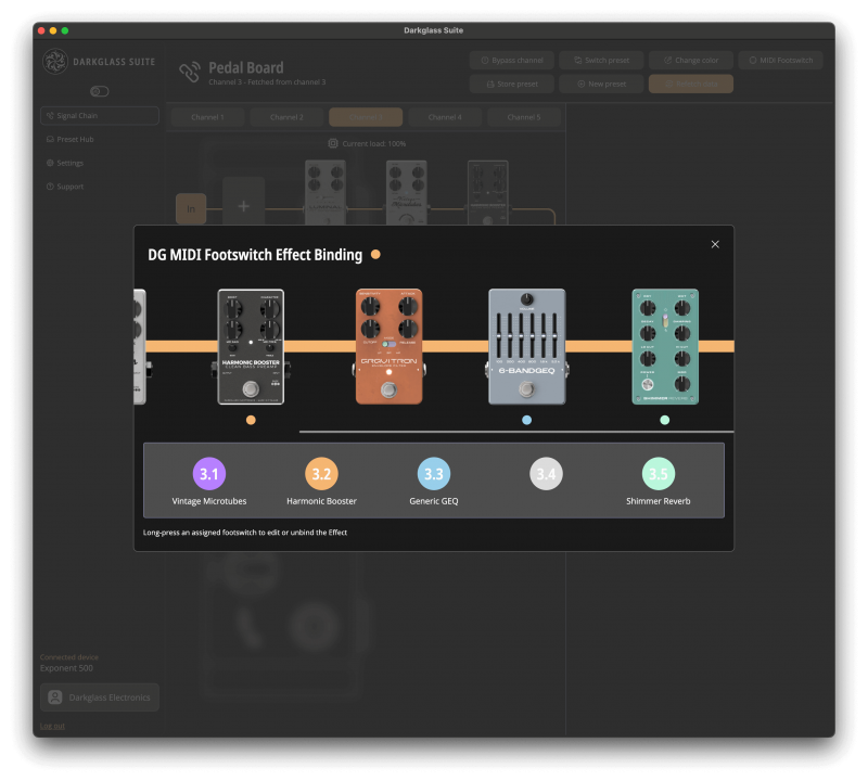
- First select one of the effects and then select the footswitch to bind it to in the pop-up window:
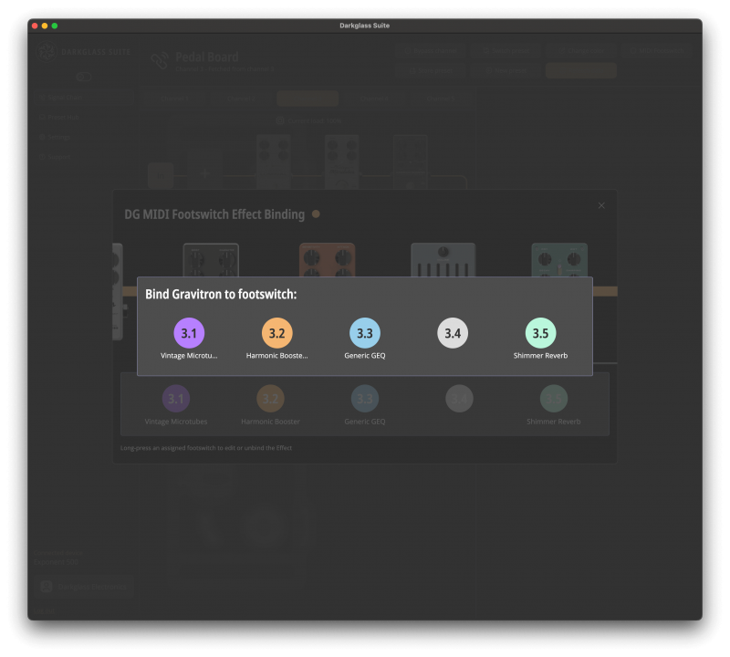
- Long press an assigned footswitch to edit or unbind the Effect
Please note that after any changes to the footswitch bindings or signal chain of a preset, you will need to resync the MIDI footswitch by connecting the USB-C cable between the MIDI Footswitch and the Exponent 500. Changes to effect parameters other than bypass are independent from the MIDI Footswitch and don’t require a resync.
Please note that if the Exponent 500 sync has been enabled for the MIDI Footswitch but it hasn’t been synced with the Exponent 500 after that, all the LEDs will be dimly lit white and the MIDI Footswitch is unresponsive to footswitch presses until synced or another configuration is chosen from the MIDI Footswitch Suite.
Infinity 500 Combo
For the Infinity 500 Combo, the default configuration is the same as the MIDI Footswitch factory default: Each footswitch selects one of the 5 presets and pressing the same footswitch again mutes the device, also accessing the Tuner.
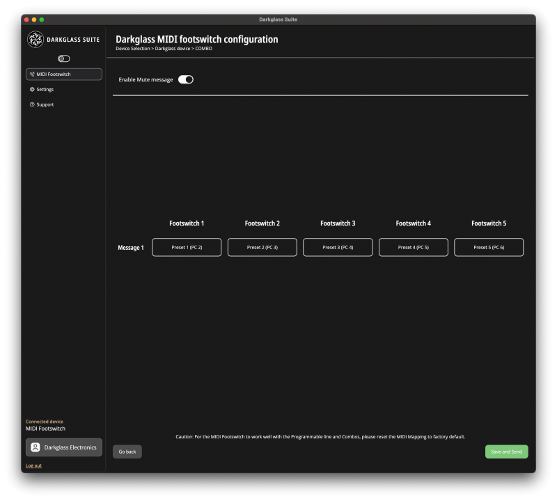
By clicking a message, the message for the corresponding footswitch can be changed to one of the presets 1-5, Bypass or Mute. The Enable Mute message toggle determines whether a second press of the same footswitch sends a mute message or not. Muted channel is indicated by a blinking LED (from firmware 1.3 onwards).
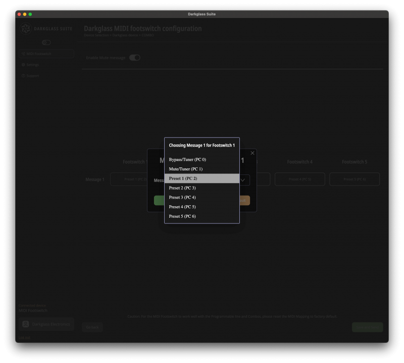
Press the Save and Send button to apply the configuration to the MIDI Footswitch.
Please reset the MIDI mapping of your Infinity 500 Combo to factory default for these configurations to work properly.
Setting up for a Generic MIDI device
Generic MIDI Device option allows you to build your own MIDI message matrix and to define sets of MIDI messages sent with a single press of a footswitch.
Page Modes
There are two available options, Single page mode and Multi page mode.
In the Single page mode, you can add up to 24 commands (program change / control change) to be sent simultaneously from the MIDI footswitch on each footswitch press. The order of the messages is the order in which the messages are sent, from top to bottom.
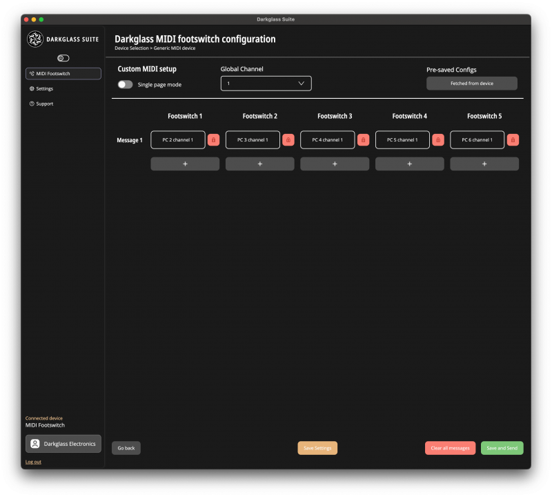
In the Multi page mode, you have 6 pages, the top page and 5 sub pages to configure a custom set of MIDI messages to. You can add up to 4 simultaneous commands to be sent on each footswitch press.
Choose a page from the dropdown selection Page to configure the messages for all the footswitches on that page. The footswitch will also move to the page selected in the Suite.
Each page has its own color of LEDs which is also visible on the Suite around the Page selection and the messages.
- Top page: WHITE
- Sub page 1 (Footswitch 1.1-1.5): PURPLE
- Sub page 2 (Footswitch 2.1-2.5): ORANGE
- Sub page 3 (Footswitch 3.1-3.5): BLUE
- Sub page 4 (Footswitch 4.1-4.5): RED
- Sub page 5 (Footswitch 5.1-5.5): GREEN
Navigate to the sub page by long pressing a footswitch on the Top page. For example long pressing the footswitch 4 moves you to the sub page 4 and turns the LEDs red. Short pressing a footswitch then sends the messages defined in Footswitch 4.1-4.5 configuration. Long pressing any footswitch moves you back to the Top page indicated by the white LEDs.
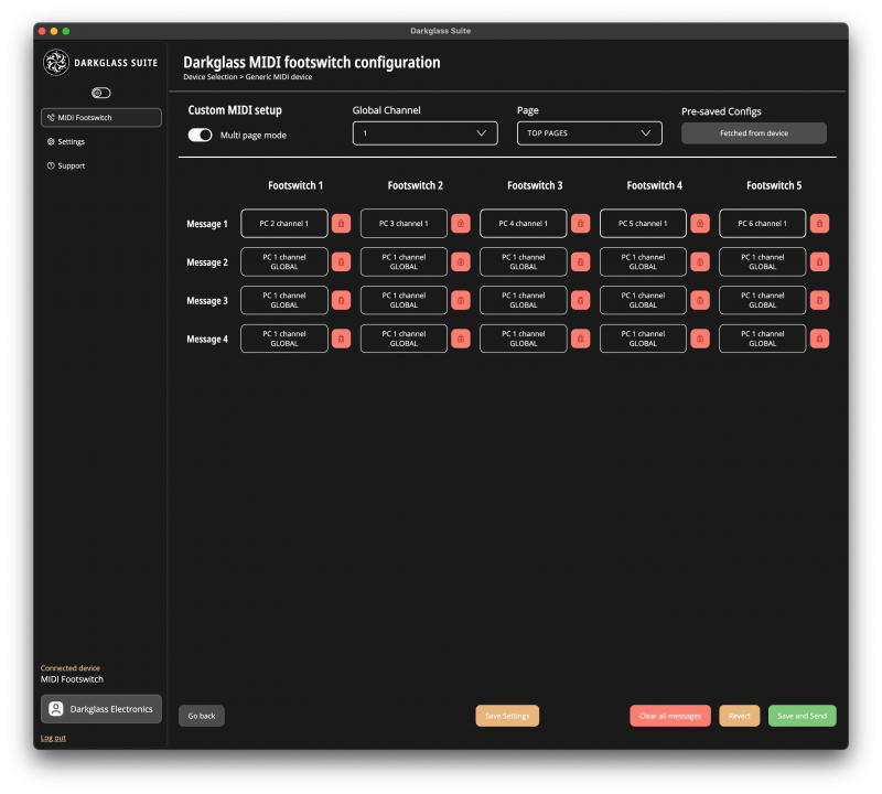
Note that moving between the Single page mode and Multi page mode will reorder the configured messages to the footswitches and pages because of the different maximum number of messages per footswitch.
LEDs in the generic mode
With firmware 1.3 or newer, the LEDs will indicate which footswitches have been assigned messages in the generic mode. If one or more messages have been assigned, the LED of that footswitch will be dimly lit, or brightly lit if it is the last footswitch that has been pressed. A push of a footswitch and sending of message(s) on an already lit up LED is indicated by a quick blink. If no messages are assigned on the whole page, all the LEDs will pulsate in the color of the page.
MIDI channels
MIDI channels are communication pathways between MIDI devices. There are 16 MIDI channels available and each can be assigned to a different MIDI device.
Selecting the OMNI channel will use all the 16 channels simultaneously. If OMNI is assigned to a message, that message will be sent to all 16 channels.
Global Channel
The dropdown selection of Global Channel allows you to choose a global channel (including OMNI). The selected Global Channel will be used for all messages which have the channel selection GLOBAL. When Global Channel is changed, the change is applied to all existing messages whose channel selection is GLOBAL.
Messages
You can add messages to the footswitch on the selected page by pressing the plus button and remove them by clicking the red trash bin.
Edit the messages by clicking them. A pop up for message configuration opens up.
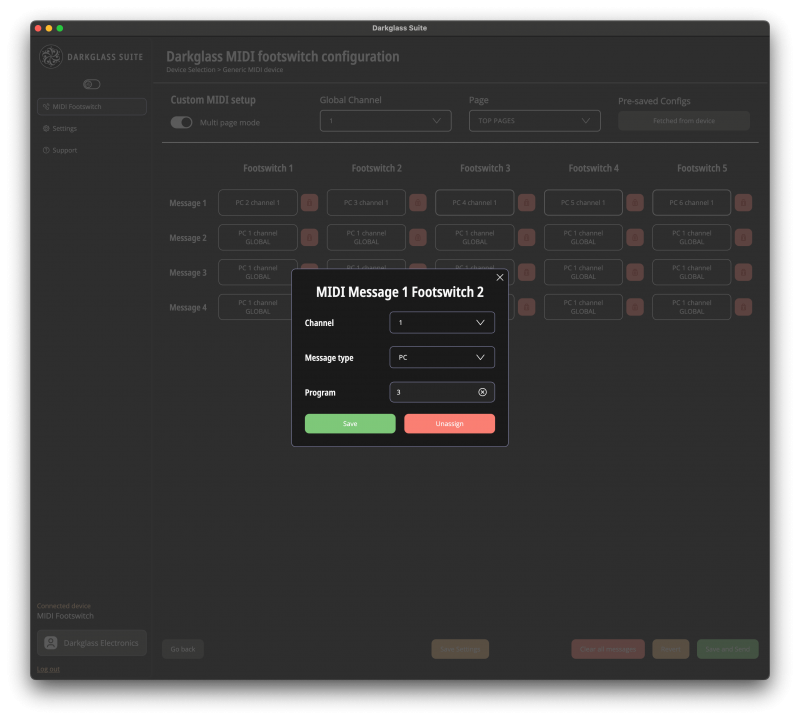
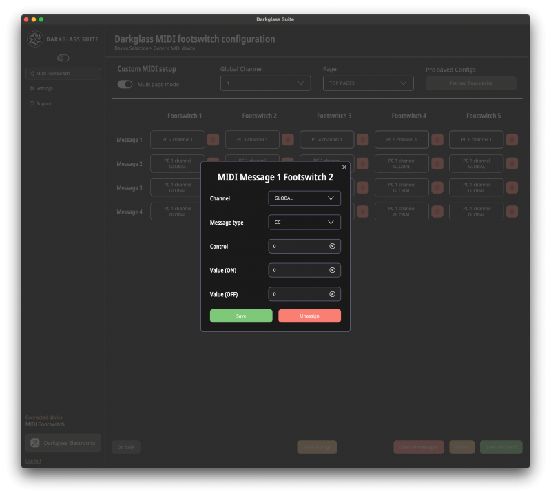
Message options:
- Channel: GLOBAL, 1-16 and OMNI. This is the MIDI channel to send the message on. See above explanations for
- OMNI and GLOBAL.
- Message type: PC (Program Change) or CC (Control Change)
- Other options depend on message type
- PC: Program number 0-127
- CC:
- Control number 0-127
- Value (ON) 0-127
- Value (OFF) 0-127
CC message ON/OFF values
CC messages have a separate value for ON and OFF. If the same value is set for both, each press of the footswitch will send the same value. If different values are set, the first press will send the ON value, the next press the OFF value, the next one the ON value and so on. This allows you to for example assign an ON/OFF type control on the receiving device to the footswitch and allow the MIDI footswitch and the receiving device be in sync regarding this control for the duration of the session. In multi page mode, the ON/OFF state of the footswitch of a specific page will persist even if you go to another page and use the same physical footswitch for something else in between. Rebooting the MIDI footswitch and changing the configuration from the Suite will reset the footswitch state to OFF meaning that the first message to send is again the ON value.
Managing configurations
Once you are done with configuring the messages of your choice, click the green Save and Send button to send the configuration to the MIDI Footswitch. Now each footswitch press should send the MIDI message(s) according to your configuration.
Revert allows you to undo the changes to the messages and Global Channel done since last Sending the configuration to the MIDI Footswitch. The configuration visible on the Suite will then correspond to the configuration on the device.
Clear all messages allows you to start from scratch by removing all the configured messages.
You can also Save your configuration in the Suite by clicking the yellow Save Settings button:
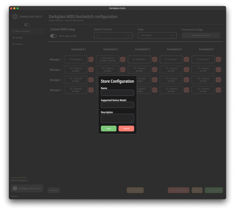
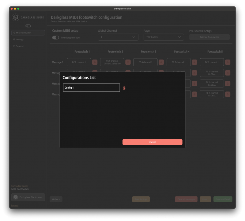
The saved configurations can be found and loaded by clicking the button under Pre-saved Configs:
USB MIDI
The MIDI Footswitch routes MIDI messages in and out through USB also (requires firmware 1.3 or higher). The routing is the following:
|
MIDI Routing
|
Destination | ||
| MIDI OUT/THRU connector | USB (to computer) | ||
|
Source
|
MIDI Footswitch | x | x |
| MIDI IN connector | x* | x | |
| USB (from computer) | x | ||
* MIDI THRU can be disabled in the Darkglass Suite > Settings
Firmware updates
The MIDI Footswitch supports firmware updates over USB using the Darkglass Suite.
The Darkglass Suite will automatically notify of an available firmware update.
Current firmware version and firmware updates can be found on the Settings tab in the Darkglass Suite.
During the update, please do not disconnect the MIDI Footswitch or close the Suite.
Dimensions
Width: 276 mm / 10.8″
Length: 54 mm/ 3.1″
Height: 54.6 mm / 2.1″
Weight: 475 g / 1.04 lb
Warning
The MIDI Footswitch has a current draw of 15mA. Only use a regulated 9V DC adapter with a center-negative plug. Unregulated power supplies and/or higher voltages may result in suboptimal noise performance and even damage your unit, voiding the warranty.
Warranty
To activate the warranty, we encourage you to register your product on: http://mypedal.darkglass.com and enter the serial number on the back of your pedal. Please contact us via email support@darkglass.com before shipping a product to us.
Disclaimer
In the interest of continuous improvement, specifications are subject to change without notice. If you have any questions, please don’t hesitate to contact us at www.darkglass.com The manufacturer claims that the above product fulfils the requirements as set by EN55013, EN55020, EN60555-2, EN60555-3, RoHS, WEEE.
1176®, and SSL® are registered trademarks of their respective companies. Names of factory modes are intended for descriptive purposes only and should not be construed as an endorsement or affiliation with the companies
or products named.
EMC / EMI
This equipment has been tested and found to comply with the limits for a Class B Digital device, pursuant to part 15 of the FCC rules. These limits are designed to provide reasonable protection against harmful interference in residential installations.
This equipment generates, uses and can radiate radio frequency energy and, if not installed and used in accordance with the instructions, may cause harmful interference to radio communications. There is no guarantee that interference will not occur in a particular installation.
If this equipment does cause harmful interference to radio or television reception, which can be determined by turning the equipment off and on, the user is encouraged to try to correct the interference by one or more of the following measures:
- Reorient or relocate the receiving antenna.
- Increase the separation between the equipment and receiver.
- Connect the equipment to an outlet on a circuit different from that to which the receiver is connected.
- Consult the dealer or an experienced radio/TV technician for help.
Corporate Contact
Darkglass Electronics Oy
Elimäenkatu 20, 00510
Helsinki, Finland
Engineered in Helsinki, Finland.
www.darkglass.com